|
|
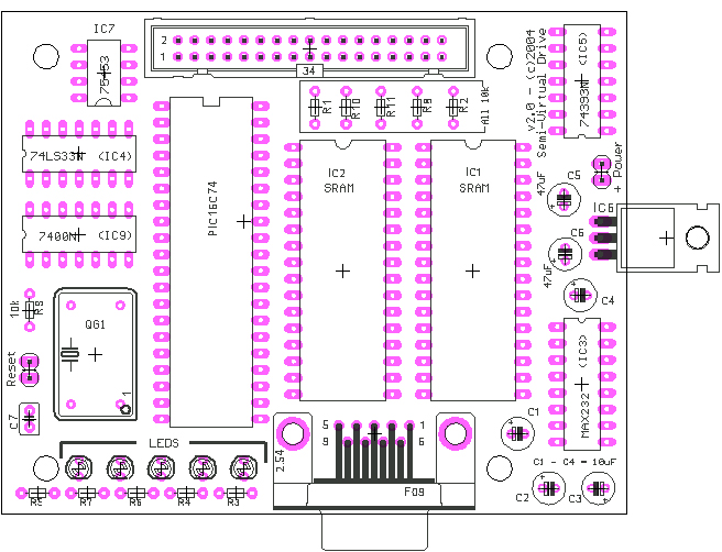
For more information on the parts, including placement and pretty pictures,
please see the assembly instructions.
| ICs |
| IC1 & IC2 | | TC551001CP | | 128k x 8 static RAM | | or any compatible SRAM |
| IC3 | | MAX232 | | RS232 serial interface | | |
| IC4 | | 74LS33 | | Quad OC NOR | | |
| IC5 | | 74LS393 | | Dual 4-bit counter | | |
| IC6 | | 7805 | | 5-volt voltage regulator | | |
| IC7 | | 75452 | | OC Line driver | | mistakenly labeled as 75453 in schematic |
| IC8 | | PIC16C65b | | MicroChip PIC processor | | can use the 16C74b as well |
| IC9 | | 74LS00 | | Quad 2-input nand | | |
| Discrete |
| R1-R2, R9 | | 10k ohm resistor | | pull-ups | | |
| R3-R7 | | 470 ohm resistor | | LED drivers | | |
| R8,R10,R11 | | 1k ohm resistor | | drive-select pull-ups | | |
| C1-C4 | | 10 uF electrolytic cap | | MAX232 caps | | |
| C5-C6 | | 47 uF electrolytic cap | | power supply caps | | |
| C7 | | 1 uF cap | | noise filter cap | | |
| Other |
| LEDs (x5) | | Minature LEDs | | | | I used 3 green and 2 yellow |
| QG1 | | 20 MHz Oscillator | | | | |
| Hardware |
| SV1 | | 34-pin box header | | | | |
| X1 | | 9-pin sub-D | | female RS232 connector | | |
| JP3 & JP2 | | 2-circuit pin header | | | | |
| - (2) | | 2-circuit connector | | | | |
| - | | SPST Toggle | | power switch | | |
| - | | SPST Momentary Pushbutton | | reset switch | | |
| - | | Power Jack | | 2.5mm | | |
| case | | Serpac 151 | | | | can use the 251 also |
Eagle Source Files
Version 2.0 - Schematic File (212 kB)
Version 2.0 - PCB (board) (91 kB)
Version 2.0 - Printable Schematic (813 kB)
Version 2.0 - PCB Parts Layout (281 kB)
PCB Manufacturing Files (Gerbers)
Version 2.0 - Zip of all Gerbers (57 kB)
|
The SVD is implemented using a PIC 16C65B. You can download
the firmware here:
PIC v2.3 firmware (70 kB).
Firmware Files
There are 5 types of files in the firmware zip
file as follows:
| vd.mcp | The MicroChip IDE project file.
You need to download the IDE to work with this file, though
it isn't completely necessary if you have a compatible assembler.
Note, however, that one include file "p16c74b.inc" (in vd.h) isn't included
in this distribution as it is part of the MicroChip IDE.
| | linker.lkr | Definitions of the sections and code pages when assembling
the code for the PIC. Pretty standard stuff. Originally a copy
of one of the PIC linker files.
| | *.asm | all files ending with .asm - These are the main code
files for the SVD firmware. Note, however, that much of the
code doesn't reside in these files. Instead, many
include .mac or "macro" files. Normally
macro files are used when macros are used repeatedly throughout
the code.
| | *.h | all files ending with .h - These files define
basic parameters (like memory locations) and also define functions that
will be called from other files.
| | *.mac | all files ending with .mac - These files
have normal "code" but are defined as macros which are included
throughout the .asm files. Often these macros are used
repeatedly throughout the code. Though in some cases the macro
was defined in preparation for repeated use, but may only
be used once.
|
Firmware Notes
| Overview | The firmware has two basic jobs: communication with the PC over the
serial port, and pretending to be a floppy drive to the vintage computer.
PC communication is accomplished through the PIC serial communication
hardware, and is interrupt driven. Floppy emulation operations are not
interrupt driven.
Floppy emulation is sector driven. Each sector has a leading byte that
dispatches to a routine that generates data in the format indicated for that
sector. The one exception to this rule is the Apple NIB format which generates
an entire track depending upon the format indicated for the first sector.
| | Code Comments | You will notice that within critical sections of the code the comments
at the end of the line of code often has a number (positive or negative)
within parenthesis after the semi-colon but before the actual comment.
This number is a reminder of the instruction cycle count remaining (or until)
the next pulse is scheduled to be generated. In most cases, the pulse/data cells
are separated by 20 instruction cycles (4 us per cell). You should be able
to see that "0" is reached when a pulse is generated.
| | Macros | Macros are liberally used throughout the code.
Some of the more interesting and heavily used are:
| Raise/Lower | When this project started, I didn't know what polarity the
signals would end-up being - positive or negative logic.
In portdef.h you will see that the signals can
be easily defined with either positive or negative logic
and that Raise and Lower cause the signal to go high or low
in concert with the type of logic used. You will also notice
that each signal ended up with negative logic...making this
set of macros superfluous.
| | WaitXX | Where "XX" is one or two numerical digits.
This macro is used EVERYWHERE, and causes a "wait" for the
given number of instruction cycles. However, the wait will
execute a HeadCheck (see below) as many times as possible
while waiting. Note that different wait's are called depending
upon which code page we are operating in.
| | HeadCheck | Checks to see if a head move is being requested by the driving
vintage computer. The head move line is sampled, and if a head
move is being requested, the code dispatches to the movement
routine. When head movement occurs, all bets are off regarding
the timing for the pulses...which is OK. As with WaitXX
different HeadChecks are called depending upon the code page.
|
| | Code Pages | The code uses 2 pages of instruction memory on the PIC.
It is split fairly evenly between the two, and great care
is taken to make sure that the right calls are done in the
right pages. Things do flip back and forth in the code as
necessary.
| | Memory Interface | As you can see in the schematic, the lower 8 bits of memory
are driven by a counter as opposed to the PIC. The PIC
simply pulses the memory increment line to bump the lower
8 bits of the address. The upper bits of the address are
separated into a hi-block and low-block address. Critical
sections of the code assume that the low-block address can
simply be incremented - the address will not roll-over requiring
the hi-block address to be incremented. This behavior is
ensured by picking the appropriate starting addresses for
the blocks as well as accounting for appropriate increments and
decrements when moving from track to track.
| | Serial Protocol | The serial.asm code implements a
serial protocol for communicating with the PC.
Details on this protocol can be found
here.
| | Sector Size | Note that the code plans for different sector sizes.
No sizes other than 256 are implemented currently.
|
When you order the SVD in "kit" form, it comes with an assembly manual.
You can also download the manual in a few forms:
Special note for the "Booklet" format - there are two files for this
format: "front" and "back". These were produced for an inkjet printer, so the order of the pages
are set to making printing on an inkjet easy. The order of the pages for the "front" file
is: page 1, 2 , 3, 4, 5. The order of the pages for the "back" file is: 5, 4, 3, 2, 1.
So when using an inkjet, print the front, then just take the pages from the output tray
and put them back in the input tray.
| The Microsoft Word format is available too. But it
is so big (22 MB) we don't post it here normally
because it takes up so darn much disk space. If you would like a copy of the Word
document, please contact us.
|  |
|


