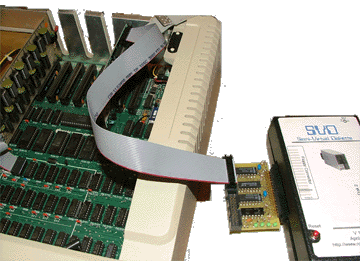
|
|

|
dongle |
"dong - gull" - noun
an extra piece of hardware that
provides auxillary function to an existing device which
usually hangs off of the existing device. |
| When created, the Apple ][ had a very innovative floppy
interface mechanism that was cheap, robust, and worked
quite well. However, it is also quite different from
the floppy interface mechanisms employed by the majority
of the other equipment makers of the day.
Since the SVD was designed to work with the majority of
floppy interfaces of that time, it requires an extra piece
of hardware, or dongle to match the Apple interface
to that provided and expected by the SVD. Fortunately, this
extra hardware is small and attaches directly to the SVD.
With the dongle, the SVD will work well with your Apple ][.
|


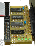
Click on the image below for a close-up.

|
Functions of the Dongle
There are three main functions that the dongle provides:
| Head Stepping |
The Apple 2 uses low-level stepper motor phase pulses to
manually advance the track head through the separate
tracks of the floppy. The dongle converts these phase pulses
into a direction signal and a step
pulse based upon the direction of the progression of the pulses.
In addition, the dongle ensures that the phase pulses coming from the
Apple are the appropriate width since, when booting, the Apple actually
holds the phase 0 pulse high for an extended period.
|
Signal Polarity |
The logic sense (polarity) of the Apple 2
signals are often the inverse of those for the "standard" floppy controllers.
This includes inverting the read and write lines as well as creating a
"motor_on" signal based upon the drive select signals.
|
Signal "Levels" |
Closely related to the signal polarity,
it is also necessary for the dongle to provide
for the open-collector signals used in standard floppy controller implementations.
This includes adding pull-up resistors for OC signals as well as creating
an appropriate tri-state level for the read signals going back to the
Apple controller.
|
Circuit Description
Stepper Pulses |
The head movement mechanism for the Apple is direct
drive pulses targeted toward the stepper motor in the floppy hardware.
These pulses are labeled phase 0 through phase 3.
When the Apple wants to seek the floppy head to another track, it
will pulse these phase lines causing the disk stepper motor to
advance either "in" or "out" depending upon the
previous phase.
For example, if the last pulse was on phase 1, a pulse on
phase 2 will step the disk drive head out, whereas a pulse
on phase 0 will step the disk drive head in.
Normal Apple "full-tracks" are positioned on phase 0 and phase 2.
"Half-tracks" are positioned on phase 1 and phase 3.
Normally, data is only written on full-tracks.
Some copy-protected diskettes/images, however, use half-tracks.
The Apple dongle circuit supports only full-track positioning.
The SVD floppy interface requires a head-step pulse
to move the head. In addition, it uses another logic signal,
step-direction,
to indicate the direction of the head step. If step-direction
is high when the head-step pulse is received, then the
step in "in", otherwise it is "out".
The circuit converts the phase pulses into head-step and
step-direction.
A flip-flop (IC1) is used to remember the last half-track pulse
(phase 1 and phase 3). When a full-track pulse
is received, IC2 converts the pulse into a head-step
pulse, while setting an appropriate step-direction.
Note that there is a potential race condition here in that the
head-step pulse and step-direction pulse
change at the same time, such that a reader of the rising edge of
head-step could potentially see the wrong direction.
However, the circuitry in the SVD doesn't work on the rising edge
of the step signal. Instead, it polls the step signal and will
sample the direction after it is noticed. This eliminates the
race condition.
|
Stepper Pulse Length |
During "normal" operation, the Apple pulses the phase lines with
a short signal (on the order of a few micro-seconds).
However during boot, after seeking to track 0, it holds phase 0
high while attempting to read track data. This can't really
be considered a "pulse" according to the specifications of the
floppy signals emulated by the SVD. In fact, when this signal
is held high, the SVD will not generate data
which would potentially dead-lock the SVD upon boot.
To eliminate this problem, a one-shot 74121 (IC4) is used to ensure
that the head-step pulse is a short one.
|
Drive Select |
Fortunately, the drive select signals for the Apple two are of the
same polarity as the other floppy interfaces.
However, a motor-on signal is needed for the other interfaces
and for the SVD.
This signal is derived with an XOR on the two drive select lines.
|
Signal Conditioning |
All of the other circuitry is used to condition the signals to match
the Apple interface to the SVD interface.
| Signal |
Source |
Conditioning |
| /Read |
SVD |
The read signal from the SVD is negative logic and must be inverted
before sending to the Apple. In addition, it is an open-collector
signal that must have a pull-up resistor. Finally, instead of using
open-collector OR'ing, the Apple uses tri-state logic. So the /Read
signal must be gated by the drive select signals.
|
| /Write-protect |
SVD |
Much like with the /Read signal, the /Write-protect
uses negative logic with an open-collector signal. It, too, uses a pull-up, is inverted,
and gated by drive select signals.
|
| /Write |
Apple |
The /Write data line necessary for the SVD is generated by
inverting the Write from the Apple interface.
|
| /Write-req |
Apple |
No conditioning is necessary for the /Write-req signal.
|
| /Index |
SVD |
The /Index is ignored by the Apple.
|
| /Track-0 |
SVD |
The /Track-0 is ignored by the Apple.
|
|
Other Notes
- JP1 - should be shorted to take power for the dongle from the SVD.
- JP2 - should be shorted to take power for the dongle from the Apple
- There is only one LED driver resister because only one of the LEDs will be on at any time.
- IC3 (74368) was used because it provided gated inverters...just what the doctor ordered for this design.
|


